
Hey guys. I'm currently in the process of swapping my Eg and I have been running into millions of questions. Thanks to the guys at k20a.org because they have the patience and ambition to always help someone out. So here is my turn to try and help someone. One of the things I couldn't wrap my head around was how to wire my charge harness for my eg. So I bought a charging harness and took it apart to break it down for everyone ")
Rsx type s charge harness complete and labeled.
![Image]()
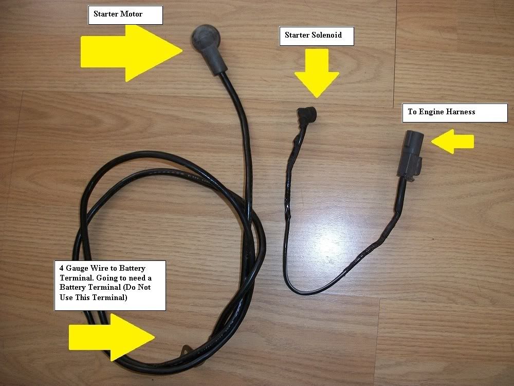
Here is what the actual charge harness consists of. The rest of the plugs you see on the "harness" itself plug into the engine harness.
You need 3 wires, (I believe OEM uses 4 gauge)
![Image]()
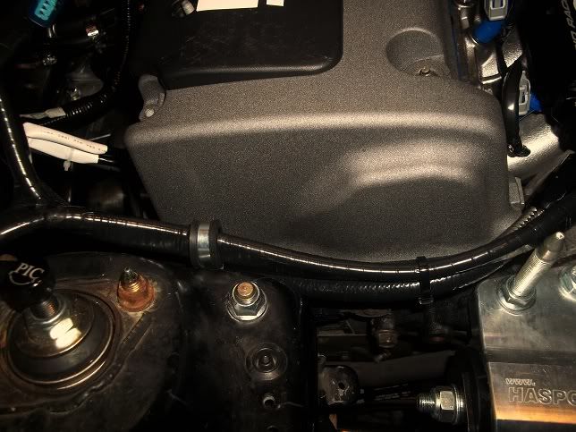
Starter wire:
![Image]()
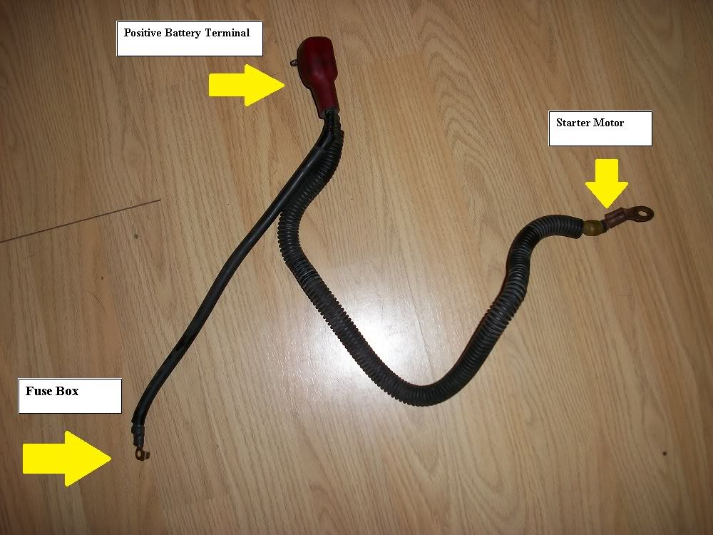
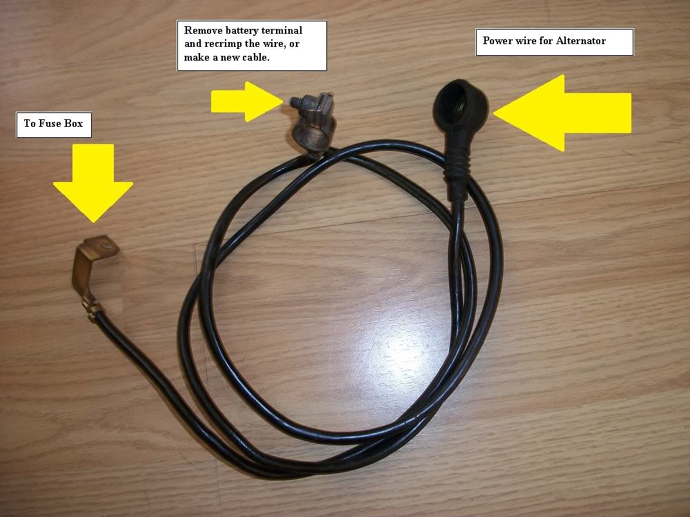
Your positive wire should look something like the d-series stock harness. You need a 4 gauge wire to go from the Battery to the Starter and a 4 gauge wire from the Battery to the Fuse box. You can cut the d-series charge harness and crimp the power wire to the starter to the power wire for the starter on the k series charge harness to extend it. I plan to make a new one so I don't have to crimp.
![Image]()
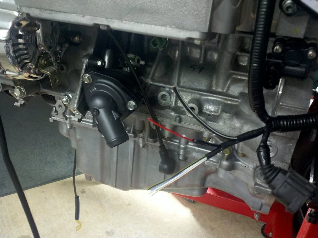
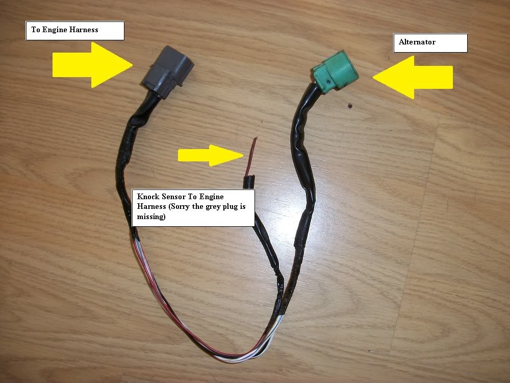
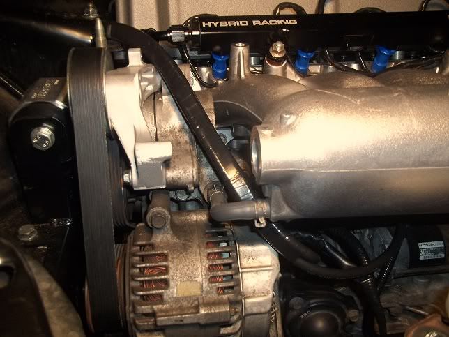
Alternator wire + Knock Sensor. Knock sensor will be on the end where the Starter Motor and Solenoid are.
![Image]()
![Image]()
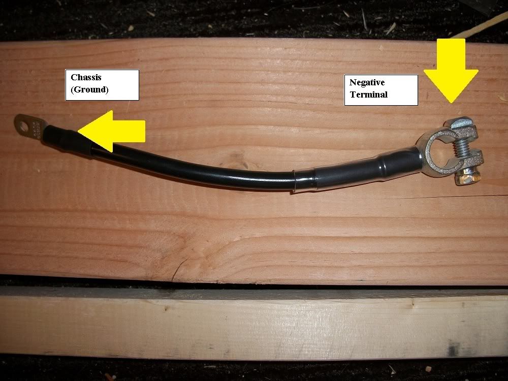
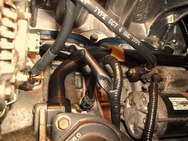
Don't forget the Ground Wire from the Battery to the Chassis
![Image]()
Updated 2/14/12
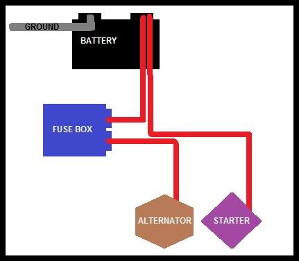
So this is the summary:
Diagram
![Image]()
Updated 6-23-12
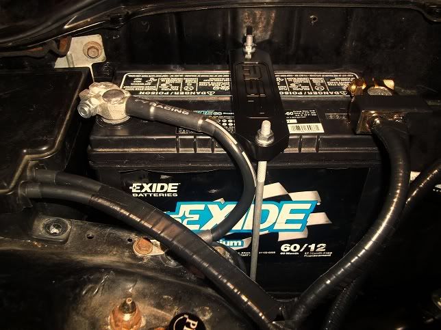
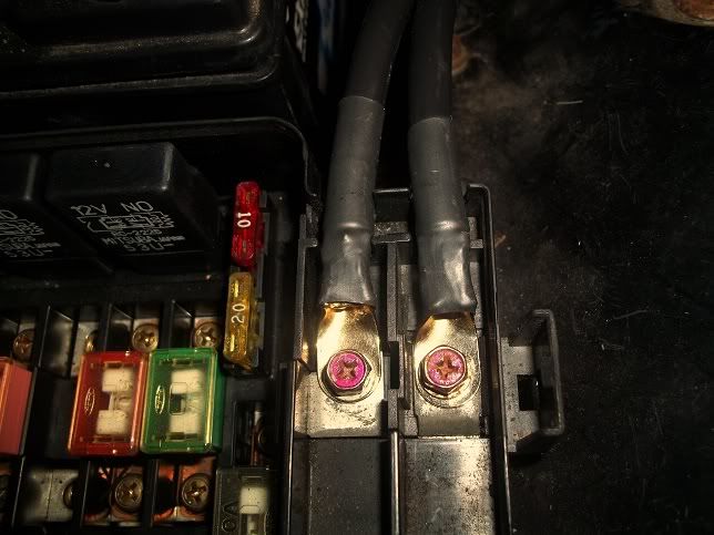
Couple of shots of the charge harness I made:
![Image]()
![Image]()
![Image]()
![Image]()
![Image]()
These are the terminals I used for the FUSE BOX and the ALTERNATOR (I used 3, 2 for the FUSE BOX, and 1 for the ALTERNATOR)
Stinger 4 Gauge Ring Terminals (1/4") Hole ( 2 Pair )
![Image]()
These are the terminals I used for the STARTER (I only need 1 but it was a pack of 2)
Monster 200 Crimpable Ring Terminals (4-gauge, 3/8-Inch Stud)
![Image]()
This was the crimper I used
Hobart 770122 Lug Crimper
![Image]()
Thanks k20a.org 🆙
Rsx type s charge harness complete and labeled.
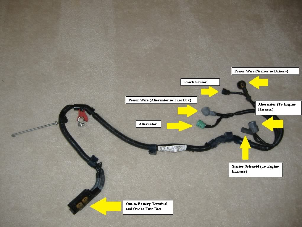
Here is what the actual charge harness consists of. The rest of the plugs you see on the "harness" itself plug into the engine harness.
You need 3 wires, (I believe OEM uses 4 gauge)
1)One wire will go from the battery to the starter motor.
2)Second wire will go from the battery to the fuse box
3) Third wire will go from your stock fuse box to the alternator
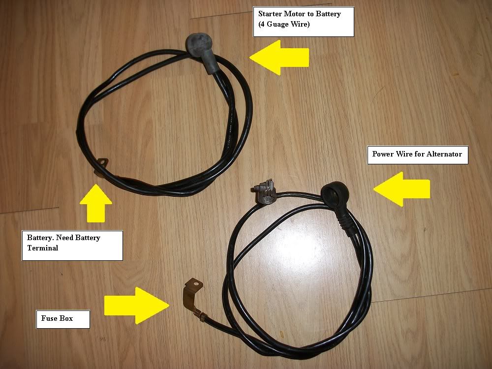
Starter wire:
Your positive wire should look something like the d-series stock harness. You need a 4 gauge wire to go from the Battery to the Starter and a 4 gauge wire from the Battery to the Fuse box. You can cut the d-series charge harness and crimp the power wire to the starter to the power wire for the starter on the k series charge harness to extend it. I plan to make a new one so I don't have to crimp.
Alternator wire + Knock Sensor. Knock sensor will be on the end where the Starter Motor and Solenoid are.
Don't forget the Ground Wire from the Battery to the Chassis
Updated 2/14/12
So this is the summary:
- 4 gauge wire (Battery to Starter)
- 4 gauge wire (Battery to Fuse Box)
- 4 gauge wire (Fuse Box to Alternator)
- 2 gauge (Negative battery terminal to Chassis)
Diagram
Updated 6-23-12
Couple of shots of the charge harness I made:
These are the terminals I used for the FUSE BOX and the ALTERNATOR (I used 3, 2 for the FUSE BOX, and 1 for the ALTERNATOR)
Stinger 4 Gauge Ring Terminals (1/4") Hole ( 2 Pair )

These are the terminals I used for the STARTER (I only need 1 but it was a pack of 2)
Monster 200 Crimpable Ring Terminals (4-gauge, 3/8-Inch Stud)

This was the crimper I used
Hobart 770122 Lug Crimper

Thanks k20a.org 🆙