Honda / Acura K20a K24a Engine Forum banner
61 - 80 of 141 Posts
Ok, for fear of being blasted, bear with me here...

What if... what if, you took the intake manifold, and chopped off the intake runner entering the cylinder furthest away from the air intake, welded and closed it off so the mani only covered the first 3 cylinders, and now you took an ITB and put it only on the last one?! Would that work?! Would that achieve somewhat of the "best of both worlds" to maintain low-end torque and yet allow for the high-rpm performance of a flute just begging for you to rev to 9-grand? :-O

Or would it just create a terrible unbalance of everything and run like crap -_-

While I thought for a min that it would create inconsistent air flow or volumetric efficiency hundreds of times each second, I also wondered if the only inconsistency would be the way the crankshaft would be being induced to run, since the air flow would be isolated. I'm thinking the only effect would be like that of a cylinder with bad compression, only it would be helping it in the high end and hurting in the low end.

Sorry for bringing up this question here, but I came across this thread recently and was as enamored by it as you guys, and hoped maybe it might find some approval here or at least technical discussion. Thanks!
 
Discussion starter · #65 ·
For an engine that sees a wide range of inlet/exhaust temps and pressures, as well as wide RPM ranges, I don't think it would be very beneficial. For something that has a pretty steady environment (rare) and only operates at one RPM (like a generator) it may be beneficial to test that idea out.

The optimum setup would have each cylinder receiving the exact same air/fuel volume, IAT, pressure, etc.

New ideas like that manifold design and runners can be tested in a fluid dynamics simulator prior to purchasing anything. You can usually get a trial version, and try out your idea. :up:
 
well if you think about it when you have an engine tuned you either have it tuned as a batch tune (not sure the actual term for it) or you tune it through individual cylinder tuning...if you tune it as a batch you have to tune for the highest possible output of the least stable cylinder...so in theory your 3+1 intake could work to make more power but it wouldnt make much power over a regular plenum...plus it would mandate the use of individual cylinder tuning, due to major flow characteristic differences, which would yield a higher output from a batch tune anyway...but it would cost hell of a lot more in tuning and design even more so than that of ITBs but with less power...i think there is some validity to it i just dont think its as viable in the end result as just getting a better flowing manifold
 
<3 this thread, I have always wondered what the best way to equalize the feeding plenum for the intake was.

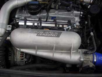
Ok, so here's my questions.

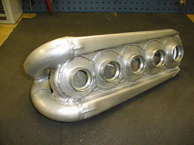
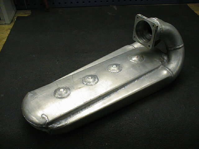
What does the size of the "slit" that the air enters the second plenum effect? I would assume that there is some form of calculation or good approximation as to the area of the entrance (or, width as we already can establish it goes across the entire IM). Quick assumption would say that too thin would become a restriction, not allowing the second plenum to fill fast enough and to starve the engine of air, but too large and you're losing out on the ability to regulate airflow and nullify the point of dual plenums.
 
Discussion starter · #70 ·
so when are we making this Puke? and whos doing it? I want in :up:
There was one person that contacted me regarding making one, but I have not heard back from them and they have not been online much since. It is something I would probably play with when I am back in the states. If anyone is interested in coming up with a design similar to the one used in the MR2 thread I linked, I would be interested in purchasing it for testing.
 
There was one person that contacted me regarding making one, but I have not heard back from them and they have not been online much since.
:sus:
 
The slit can look deceivingly small...the size of the intake ports, and valves, will determine the size of the passage between plenums.
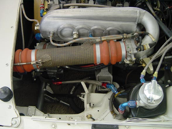
The MR2 one seems pretty small.

This is why I ask. I am going to be building an IM down the road for my 800whp build. I really want to give this a try, but if I'm going to do it I want to be able to at least have a little bit of math to back up the theory. There is a lot of work involved to do it wrong, lol.
 
Those RacerX pieces look a lot like early development experiments. I think I'd want to see real independent testing on those before I would believe they make power.

The cast and molded pieces posted up by SignalPuke appear to be much further along in the development process. This is merely my opinion, based on the casting process being more expensive and not used until the design has been finalized after much testing.
 
61 - 80 of 141 Posts