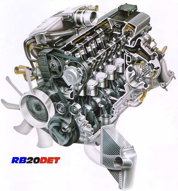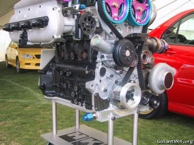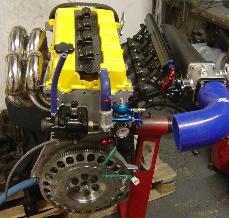

Been seeing these pop up on a couple different sites for Forced Induction applications.
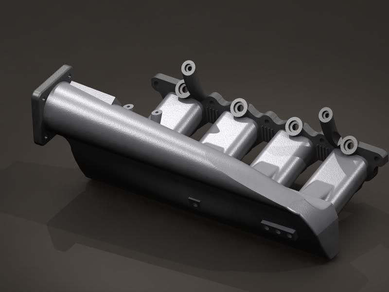
Basic idea is that they provide balanced cylinder filling, but for the K-series they would serve double duty by allowing us to run the throttle body facing the opposite direction, ideal for charge pipe routing.
Taken from http://www.bufkinengineering.com/
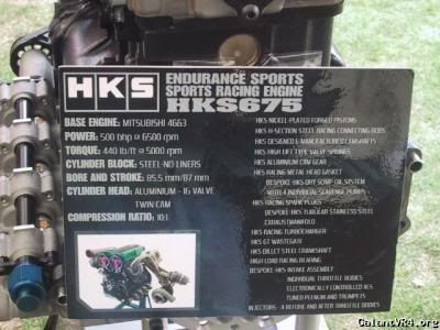
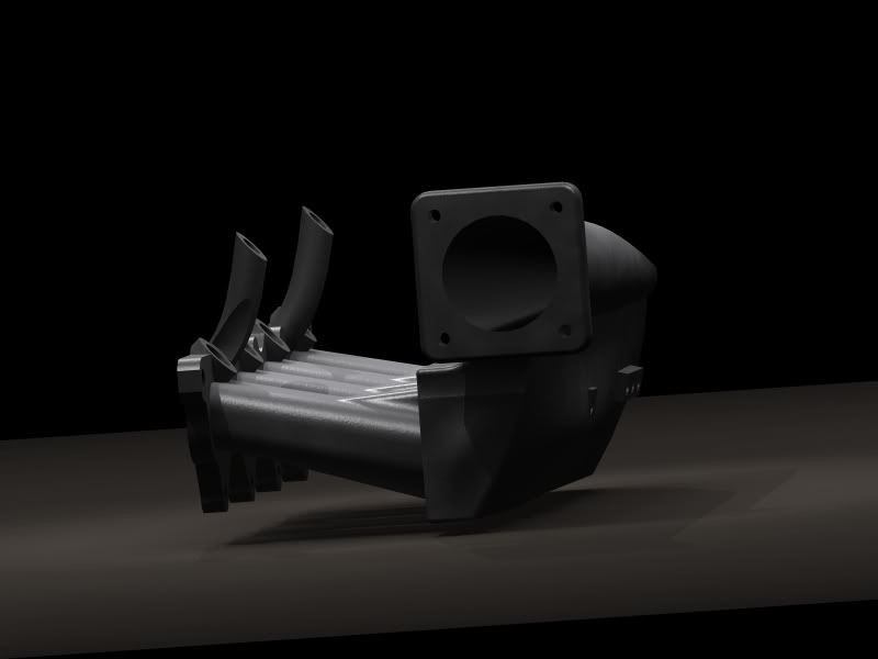
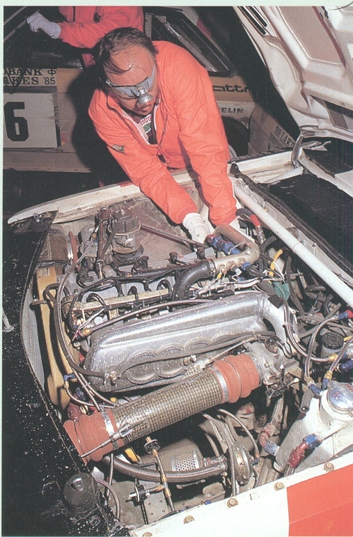
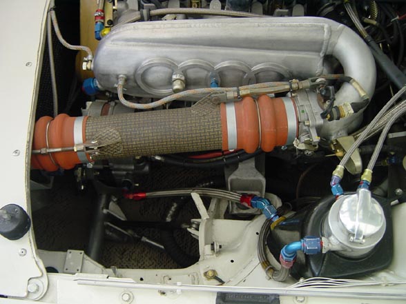
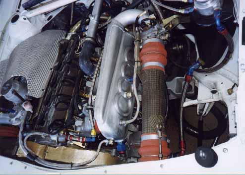
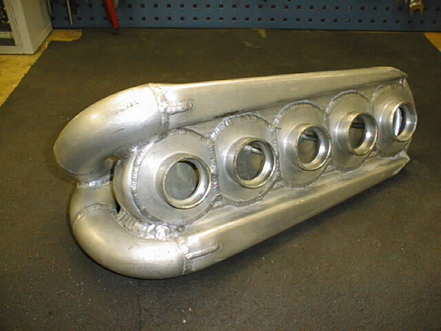
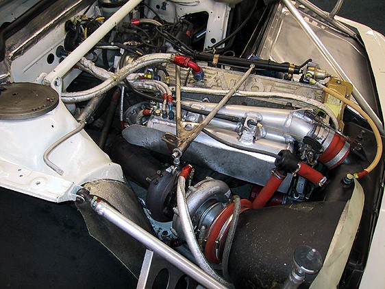
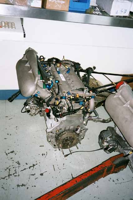
1985 Pike's Peak cars and Audi Group B S1 Evo 2 had these versions fitted:
![Image]()
![Image]()
![Image]()
![Image]()
![Image]()
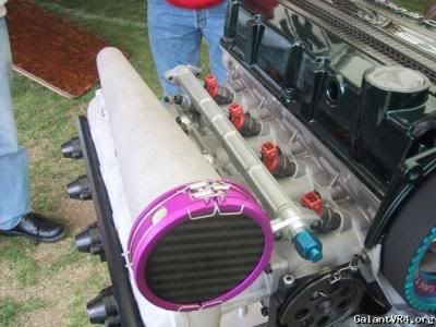
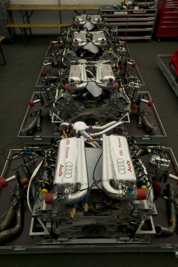
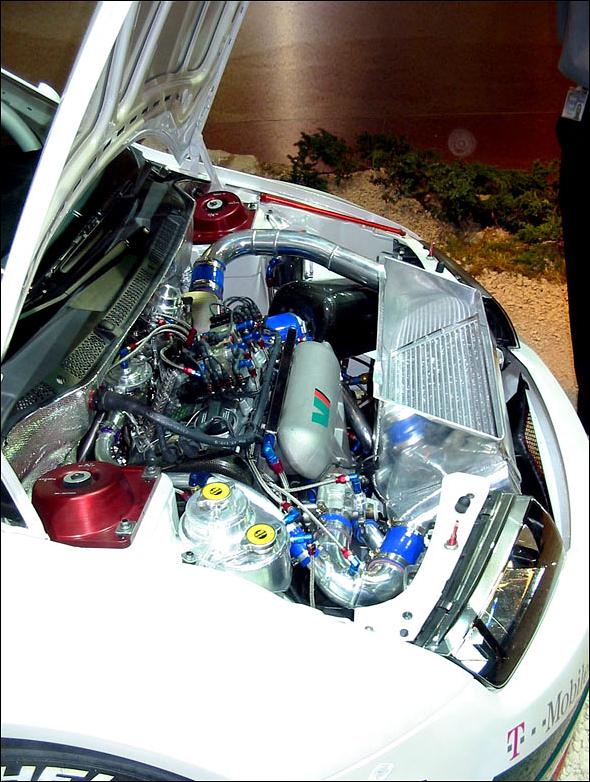
Audi R8 Le Mans car
![Image]()
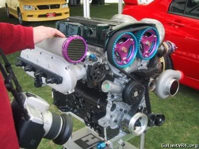
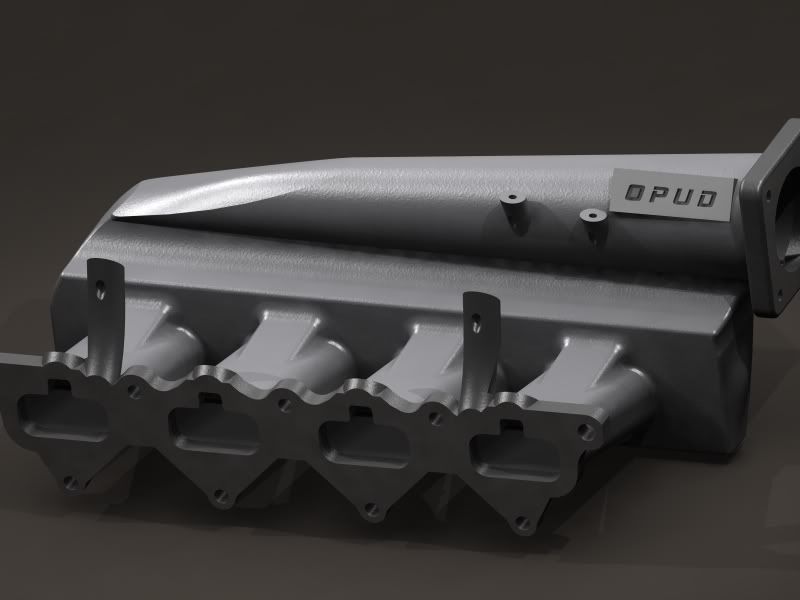
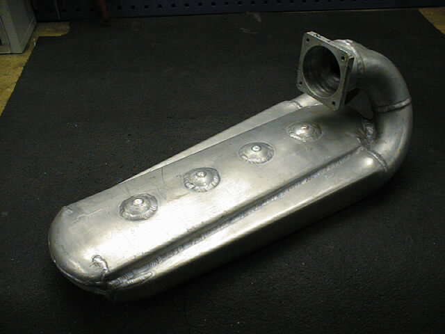
Manifolds made by Lehmann Motoren in Liechtenstein
![Image]()
![Image]()
![Image]()
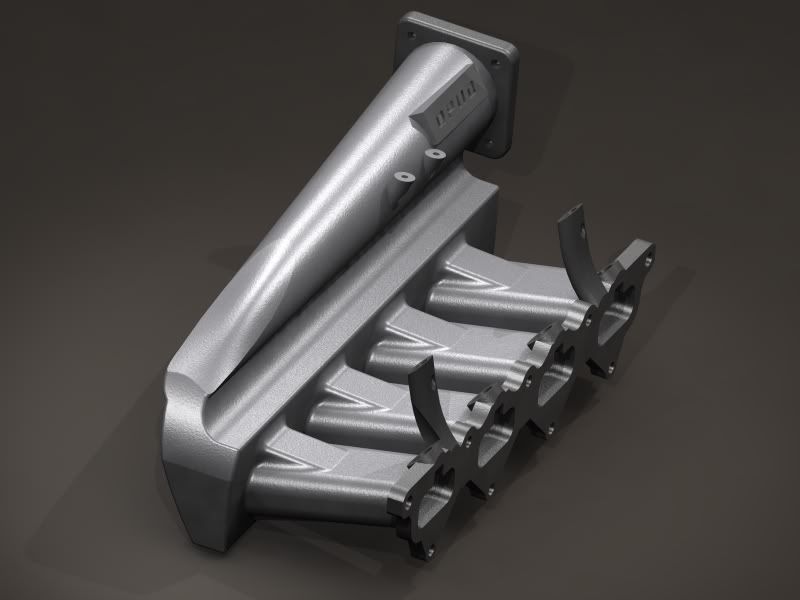
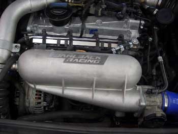
Another example
![Image]()
Basic idea is that they provide balanced cylinder filling, but for the K-series they would serve double duty by allowing us to run the throttle body facing the opposite direction, ideal for charge pipe routing.
Taken from http://www.bufkinengineering.com/
Ok, basic idea sounds good. Now some pics.
1985 Pike's Peak cars and Audi Group B S1 Evo 2 had these versions fitted:
Audi R8 Le Mans car
Manifolds made by Lehmann Motoren in Liechtenstein
Another example


")