Honda / Acura K20a K24a Engine Forum banner

Dual Plenum Intake Manifold

143K views 140 replies 34 participants last post by  Tid  
#1 ·
Been seeing these pop up on a couple different sites for Forced Induction applications.

Basic idea is that they provide balanced cylinder filling, but for the K-series they would serve double duty by allowing us to run the throttle body facing the opposite direction, ideal for charge pipe routing.

Taken from http://www.bufkinengineering.com/
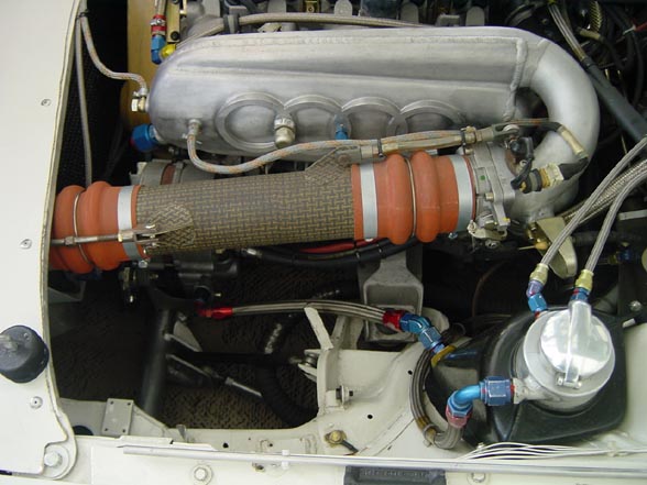
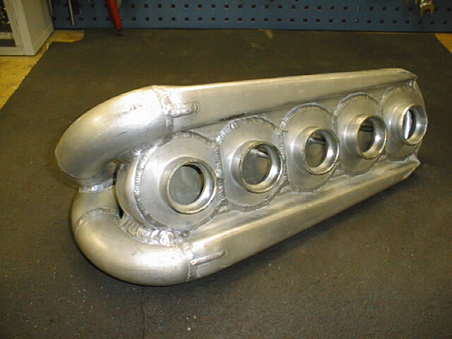
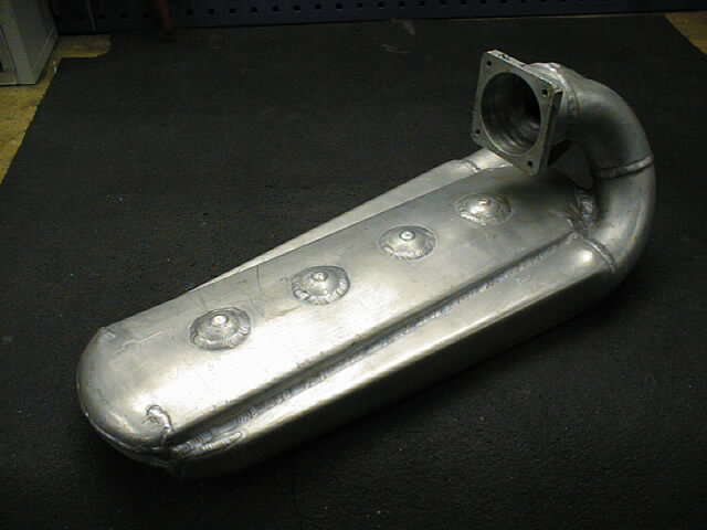
When Audi introduced the 20V motor. The car was homologated with a unique special cast intake manifold with a dual plenum. One drawback of using a single intake plenum is that after the charge air passes through the throttle body, the pressurized air isn't going to hit the runners going to the head equally. Runners closer to the front near the throttle body could very easily get more air than the cylinder furthest away. The Air velocity could play a factor in this as well. Its a very different concept when compared against a normally aspirated car where each cylinder's vacuum draws air into the cylinder so a vacuous single plenum with velocity stacks makes alot of sense. Also on a normally aspirated car, its very common to see individual throttle bodies for each cylinder to get maximum airflow with the least pressure resistance. So how does one actually design an intake manifold that allows or at least attempts to provide equal airflow to each cylinder? Well why would one even want to? If modern electronics allows a different fuel injector pulse to each cylinder, we could just adjust the fuel flow to compensate for the difference in airflow. We could do that, but does that actually give us the most efficient use of the engine's potential? Surely if one cylinder is drawing in 50 cfm of air and another is drawing in 40 cfm, the ideal thing is to get each cylinder to take 50 cfm of air. More air means more fuel and that means more power. So in a perfect engine each cylinder gets an equal amount of air. Having one cylinder running rich or lean from unequal airflow could lead to premature engine failure. So simply put. Dual plenum intake manifolds are turbocharged version of individual throttle bodies...
....Its also characterized by its large 2nd plenum which sits over the primary plenum underneath. The primary lower plenum with connects to the throttlebody is gradually tapered like a cone with a continuous single vent slot that allows gas to pass into the 2nd plenum. The 2nd plenum acts as a collector which then feeds the runners to the head. Pressure in the 2nd plenum is equallized since its not effected by gas velocity and inertia or the pressure variation from front to back of the 1st plenum. Since flow equals velocity times area. The reduction in flow which is released through the side slot is equal to the reduction in area of the plenum assuming velocity is constant. So a smooth conical taper with establish equal pressure and air distribution into the 2nd plenum.
Ok, basic idea sounds good. Now some pics.

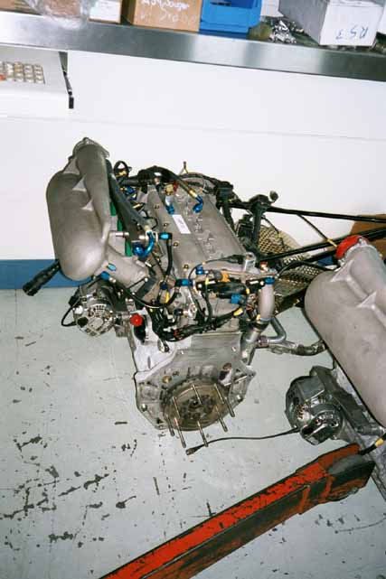
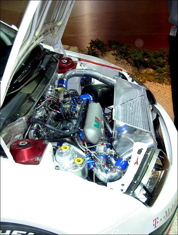
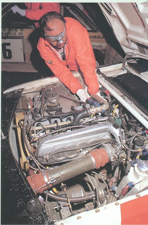
1985 Pike's Peak cars and Audi Group B S1 Evo 2 had these versions fitted:
Image

Image

Image

Image

Image


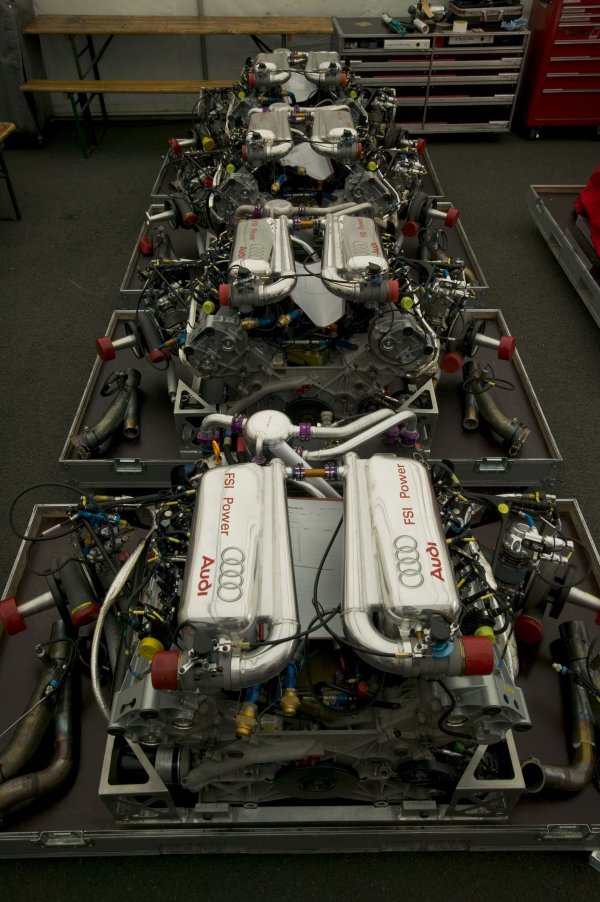
Audi R8 Le Mans car

Image


Manifolds made by Lehmann Motoren in Liechtenstein
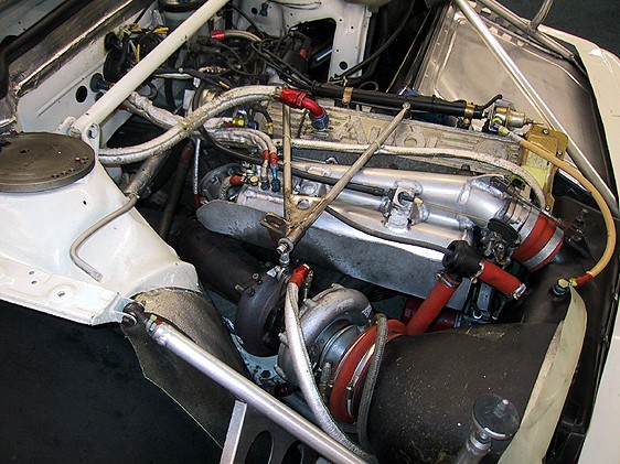
Image

Image

Image


Another example

Image
 
#3 ·
so it looks like on a boosted car it's worth about 4 whp...what about space constraints? How do these work for N/A cars?
 
#4 ·
They don't work for NA engines.
Space constraints is a non issue, the conical plenum can be mounted underneath the original plenum.
Look at the curve, the peak numbers mean nothing. Power comes on earlier. The only change on the toyota motor was the intake manifold.
 
#8 · (Edited)
#16 ·
#9 ·
A lot of Ford owners in the UK use these inlets as the world rally car used the same. The WRC ones are made of magnesium, have 8 injector holes and cost over £3k from what i've heard.

Search for MIS Cosworth Inlet Manifold on Google and see what comes up if that interests you.

2006 build of a Ford Escort Cosworth that uses a Nissan Skyline GTR R33 gearbox.

http://www.puntosports.co.uk/forums/showthread.php?t=49682
 
#12 ·
Turbo and na stuff, pcv goes into the intake plenum.

They are using a common plenum with 2 sets of runners and swirl flaps in most cars. (I dunno how I missed that before.) I am not sure about the new v8 biturbo's havent looked into it yet.

Manifolds are constructed from a magnesium, aluminum and zinc alloy.
Ill get some pics here in the next few days...
 
#19 ·
http://www.jasperintegration.com/navi.html
This is the site I found with the cone. I like the idea of having the throttle body facing the opposite direction for optimized intercooler pipe routing, only thing I am not sure about is how the accessories will fit into the mix. Might be a little tight for some applications with the motor closer to the radiator.
 
#21 ·
The only one of the pictured manifolds that was done correctly was the factory Audi setup where the laminar distribution chambers (not dual plenums) wrapped all the way around both sides of the plenum chamber. The thing you guys seem to be unaware of is that fluids don't flow into tubular holes from the top. The flow is around the periphery of the hole. This is the reason all air intakes benefit from the use of "velocity stacks", since the radius below the horizon allows the fluid to flow into the tube smoothly. A manifold that only has a laminar distribution chamber on one side of the plenum was built by someone who doesn't understand airflow!!!
 
#22 ·
Did you read the linked thread?
http://www.mr2oc.com/showthread.php?t=403005

The guy has "velocity stacks" on each runner. Gains were made, turbo spooled faster. Looks like it works to me.

Have you tested these types of manifolds before?
 
#29 · (Edited)
CSV? Temp sensor?

I don't see this being used with a roots type SC.

A centrifugal SC, or turbo setup, yes.

Most of my research has concluded that OEM plenums are compromises, usually for space.
For NA applications:
Larger plenum results in more power, but slower response to throttle input.
Smaller plenum results in less power, but quicker response to throttle input.

This 'dual' plenum is more for evening out the cylinder/cylinder variances in air mass and pressure.

Rich, check out these threads, they touch on plenum sizes and Roots type SC systems.
http://www.eng-tips.com/viewthread.cfm?qid=88498&page=78


Here is my thinking...
If the OEM 2.0L is making 200hp NA, then I would say it ingests 0.5L of air per cylinder to make that power.
The air is being pulled by the vacuum of the motor, so it is not filling the plenum very efficiently.
Going larger will facilitate the lack of filling ability of the engine vacuum...

On an FI app the air in the plenum is pressurized and if the Turbo or SC can fill the plenum fast enough, then it only needs to be that large. We run into issues when the motor is out running the turbo or SC.

There is a reason this is in the 'theory section' :D

Luckily for me, there are a ton of great dyno plots on the site for different turbo apps using an RBC manifold. Good place to start right there for determining what turbo I want to use. Adding a conical plenum to an RBC on one of these plotted motors would be an interesting test, and would show us how well the RBC is at distributing pressurized air to the different cylinders.
 
#35 ·
http://www.kinsler.com/page--Honda--18.html

http://www.honda-tech.com/showthread.php?t=2806211 :up:


"Just finished this one up, thought I'd share and make a thread for anyone with questions.

These are 100% custom, just like our ITB's.
The available plenum volumes range from 2300cc to 4700+cc (you specify)
The plenum lid is CNC'd to accept the throttle body of your choice
(this one is set up for a 90mm Wilson)

They are $2,149.90, and take approx. 4 weeks to produce."


This would probably be why you haven't seen/heard of it.
 
#37 ·
Damn.

Now I'm curious as all hell.


Don't mean to get off topic here, but.....The whole.....ITB's in a plenum thing is throwing me off. Anyone speculate how well that mani would work on an FI setup? Or is that just an N/A thing strictly?

Not sure I understand the reasoning behind this design.
 
#41 ·
Those are not ITBs. It is a single throttle plate manifold with conical trumpets inside, like the OEM.

These are air boxes for ITBs
http://k20a.org/forum/showthread.php?t=76939
http://k20a.org/forum/showthread.php?t=43478

The closer the throttle plates are to the ports the more immediate the throttle response. This is the idea behind BMW and Nissan using these ITB/turbo systems on their gran touring cars.

What I am looking for with the dual plenum is even distribution of the air to each port. Throttle response will be the same as if I were to use an RBC or the Kinsler manifold.
 
#38 ·
Ah the Kinsler intake manifolds are so sexy. Good info itt, thanks signal. I'd be willing to donate a RBC if someone wants to do the fab work. I don't really need it since I'm running an RRC and HR 70mm TB.
 
#39 ·
Ive been wanting to fabricate a dual plenum intake manifold for quite awhile. I have an RBB intake and it looks like the runner half could be used and a fabricated dual plenum bolted on for something quick and simple.

Once my car is tuned I should have a nice baseline to start testing parts like this :up:

Also we are going to start trying out a specialized manufacturing process that would easily fabricate 2 piece tapered curved runners!