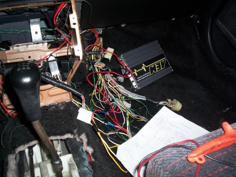

I got my swap done last week, made my own harness with no engine lights. Didn't want to wait and spent the $350. Decide to do a write-up for those who are willing to do their own. If you can read the Hondata schematic
![Image]()
, you won't have any problem.
If you can get the sub harness from the RSX to use the connectors, C101 and the E-plug. I was able to get a 02 civic sub harness, used the stock relays, but you can use universal relay, but on the civic connector it's was missing some wires that needed to be added.
So, basically you'll need the C101 to connect to the engine harness, 3 relays and E-plug to ecu. The Hondata schematic is really good, just missing the 2nd O2 and DLC which is in the manual.
For the EG
Once you get the harness made up with the 3 relays.
Unplug the main relay which you don't need anymore. Jump wires 7 and 8, this will let you tap the output from the Fuel pump relay to A7 at the stock ecu harness. Jump 3 to 5, this will let you tap the Ign signal at A25 on the stock ecu harness.
A7 for fuel pump
A25 for Ign signal
D1 for Batt+ (make sure to change the fuse under the hood from 7.5amps to 30amps.)
Main relay looks like this.
- - - -
8 6 - 2
- - - -
7 5 3 1
1 Bat+
2 GRN
3 A25
5 IGN
6 St switch
7 Fuel Pump
8 A7
These are the wires I tapped.
E15 - ELD to D10 on stock ecu harness
E22 - Brake Switch D22 on stock ecu harness
E26 - RPM to gauge
E31 - MIL to A13 on stock ecu harness
Engine Harness
3 - VSS - tap it to gauge
7 - FanC -- A12 on stock ecu harness
8 - Alt-L -- A16 on stock ecu harness
16 - Starter -- I solder it to the ignition or tap it to starter wire
18 - Oil pressure -- tap it to gauge
DLC Pin Out
The pinout at the diagnostic port is as follows:
pin 4 (BLK) = chassis ground
pin 5 (BRN/YEL) = LG3 logic ground from ECU pin E3
pin 7 (LT BLU) = "K-Line" (2-way OBDII serial communications line) to ECU pin E23
pin 9 (BRN) = SCS (Service Check Signal) line to ECU pin E29 <--
pin 12 (RED/WHT) = write-enable signal to ECU pin E30 (for rewriting the ECU)
pin 14 (GRAY) = +5V from immobilizer control unit pin 3 (probably for rewriting immobilizer codes)
pin 16 (WHT/RED) = +12V battery voltage (from #9 BACKUP fuse 7.5A)
so another way to do it would be to ground ECU pin E29, and then you should get the CEL flash code as described in the above article.
2nd O2 Pinout
O2 sensor plug
1 2
3 4
1 -- E2 - (WHT/RED) SHO2S
2 -- E4 - PNK SG3
3 -- To A/R Relay (same as the Primary)
4 -- E6 - BLK/WHT SO2SHTCR
Temp and fan switch needs to be wired.
Good luck and make sure to double check. PM if you have any ?

")